3. Reading Analog Signals with an ADC
In this tutorial, we will:
- Familiarize you with the sensors.
- Show you how to translate analog signals from sensors to digital signals using an Analog-to-Digital Converter (ADC).
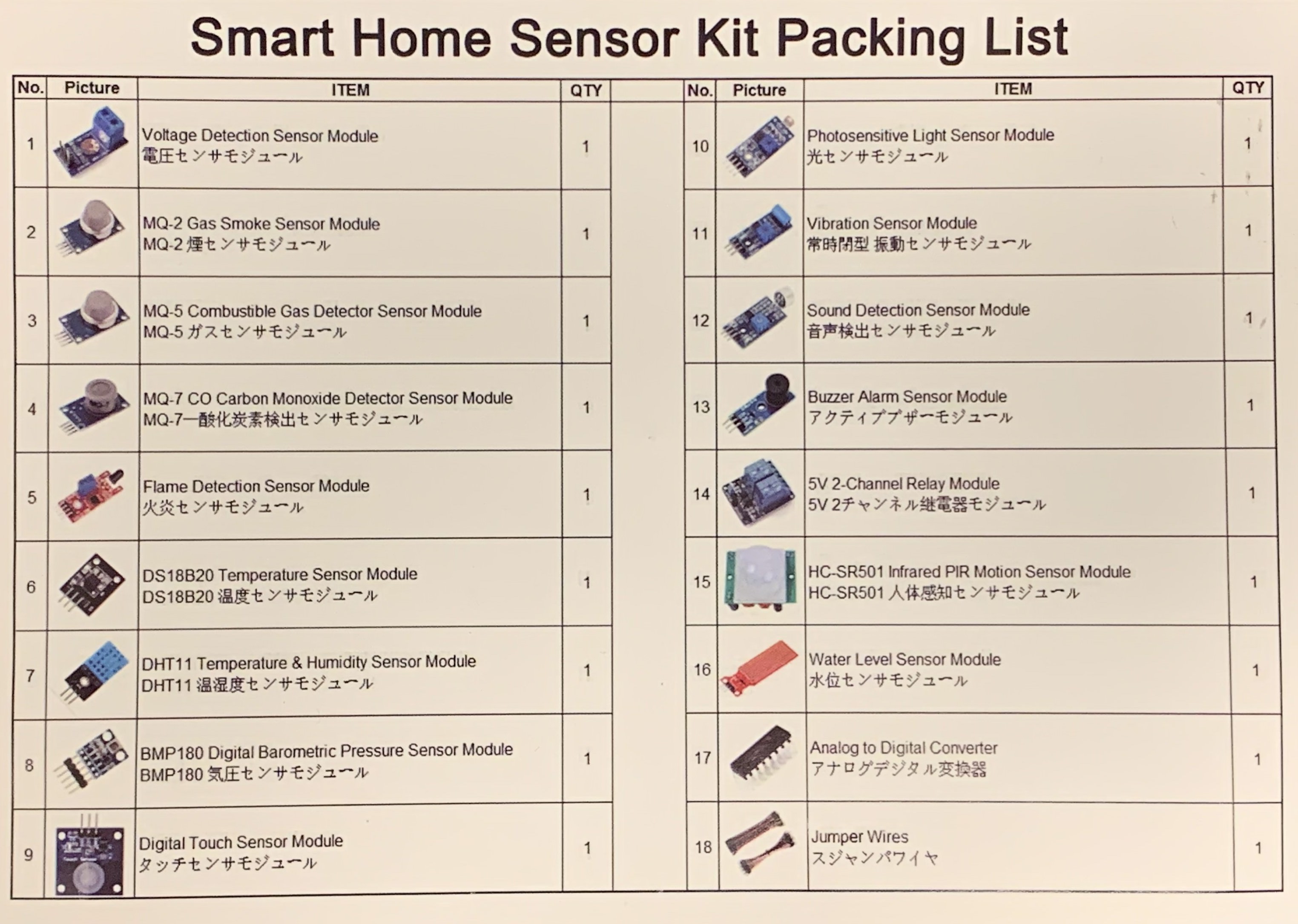
Sensor Kit
Having introduced you to the basics of RPi, we will look at how to acquire information from physical world using sensors. We provide each team with a Smart Home Sensor Kit from Kookye, which comes with a relatively good list of tutorials for the kit (though the English used in them is pretty weak).
MCP3008
The GPIO pins on RPi only take digital signals. However, signals from some sensors come in analog form. In such cases, we will use an ADC to translate the signal. We will use MCP3008 that comes with the sensor kit for this tutorial.
MCP3008 can process 8 channels of analog input with 10-bit precision. The numberings of the pins are shown below. When you read the pin numbers, be sure to align the notch on the microchip with the one in the figure. For more details, see the MCP3008 Spec Sheet.
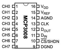
CH0-CH7 pins (Pins 1-8) are used for the analog inputs from sensors. Connect the rest of the pins to corresponding pins on the RPi with jump wires. To make sense of why things are connected this way, check out Serial Peripheral Interface (SPI) but don’t be scared if you do not understand much (or any) of it.
| MCP3008 | RPi |
|---|---|
| VDD (Pin 16) | 3.3V |
| VREF (Pin 15) | 3.3V |
| AGND (Pin 14) | GROUND |
| CLK (Pin 13) | SCLK |
| DOUT (Pin 12) | MISO |
| DIN (Pin 11) | MOSI |
| CS (Pin 10) | GPIO5 |
| DGND (Pin 9) | GROUND |
Install CircuitPython on RPi
We will use the CircuitPython package. This section summarizes this tutorial.
- Enable I2C
- Enable SPI
- Install Adafruit-Blinka library
$ pip3 install adafruit-blinka - Verify installation with
[blinkatest.py](https://learn.adafruit.com/pages/12762/elements/2993427/download), which is included among the tutorial files. - Install MCP3xxx library
$ pip3 install adafruit-circuitpython-mcp3xxx
Read Analog Outputs from a Sensor Module
In this tutorial, we will use the Photosensitive Light Sensor Module. Read more here on the physical mechanism of the sensor.
Connect the sensor module following the table.
| Photosensitive Light Sensor Module | |
|---|---|
| VCC | RPi 3.3V |
| GND | RPi GROUND |
| AO | MCP3008 CH0 (Pin 1) |
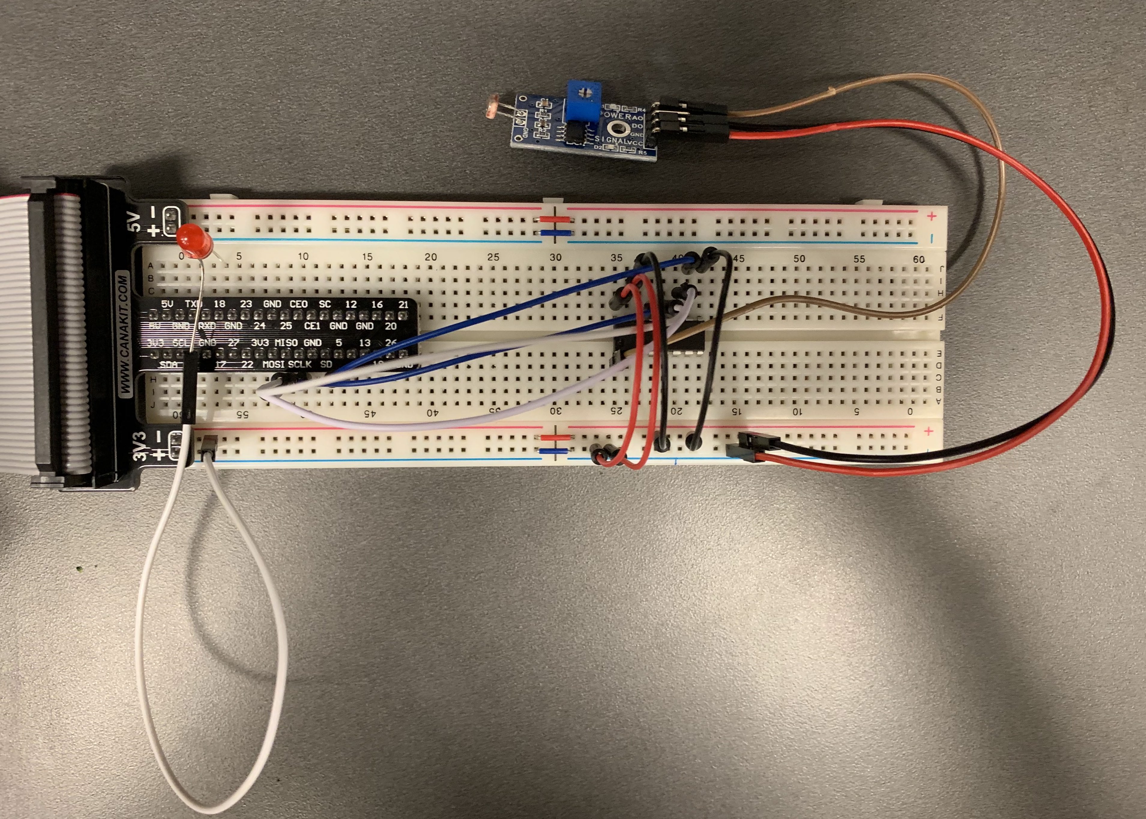
The completed circuit looks like this:
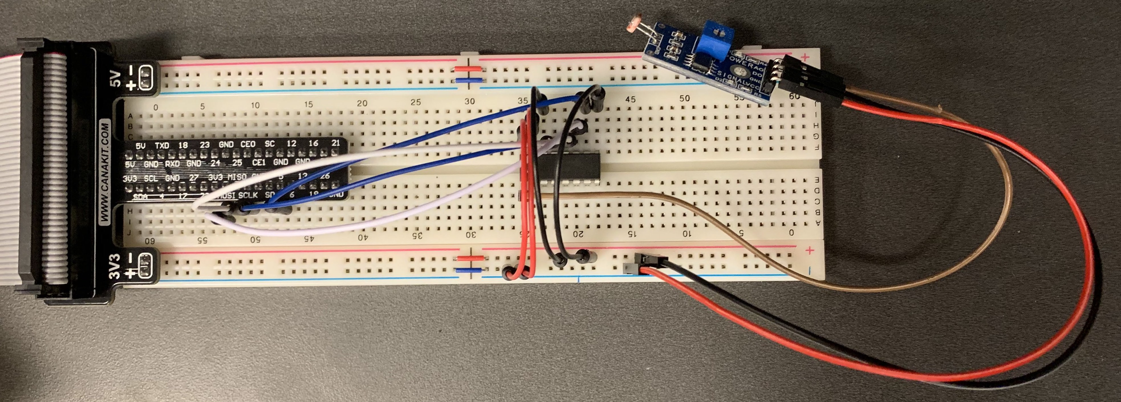
It is similar to connecting any other sensors. The label on each leg of a sensor module gives you a good idea of what it is meant for and how to incorporate it in the circuit.
| Labels on the Legs | Meaning |
|---|---|
| VCC, + | Power Input |
| GND, - | Ground |
| AO | Analog Output |
| DO | Digital Output |
| S, SIG, DATA, OUT | Signal |
Use the following code (Tutorial-3-1.py) to read the sensor outputs.
import busio
import digitalio
import board
import adafruit_mcp3xxx.mcp3008 as MCP
from adafruit_mcp3xxx.analog_in import AnalogIn
import time

spi = busio.SPI(clock=board.SCK, MISO=board.MISO, MOSI=board.MOSI)
cs = digitalio.DigitalInOut(board.D5)

# Create an MCP3008 object
mcp = MCP.MCP3008(spi, cs)
# Create an analog input channel on the MCP3008 pin 0
channel = AnalogIn(mcp, MCP.P0)

while True:
    print('Raw ADC Value: ', channel.value)
    print('ADC Voltage: ' + str(channel.voltage) + 'V')
    time.sleep(0.5)
Note that you can get a better sense of what the code above is doing if you read the documentation for the modules we are importing and making use of. For example, you would do well by reading through the docs for board, busio, digitalio, adafruit_mcp3xxx and the adafruit_mcp3xxx.analog_in class.
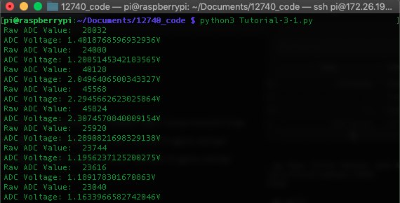
The output of the program, assuming it ran correctly, looks like this. The readings vary with the light intensity.
Control an LED based on Ambient Lighting
Finally, let’s combine what we have learned and control an LED based on ambient light intensity.
- Add an LED into the circuit, following Tutorial 2. Use GPIO18 for connection. The circuit looks like this:
- Run the following code (
Tutorial-3-2.py). The LED is controlled by the light intensity using a if-else statement. The LED is on when it is dark or the sensor is covered.
import sys
import busio
import digitalio
import board
import adafruit_mcp3xxx.mcp3008 as MCP
from adafruit_mcp3xxx.analog_in import AnalogIn
import time
import RPi.GPIO as GPIO

spi = busio.SPI(clock=board.SCK, MISO=board.MISO, MOSI=board.MOSI)
cs = digitalio.DigitalInOut(board.D5)

# Create an MCP3008 object
mcp = MCP.MCP3008(spi, cs)
# Create an analog input channel on the MCP3008 pin 0
channel = AnalogIn(mcp, MCP.P0)

# Set up GPIO
GPIO.setmode(GPIO.BCM)
red_led = 18
GPIO.setup(red_led, GPIO.OUT)

threshold = 2 # Threshold for turn on/off LED

def main():
    while True:
        if channel.voltage>=threshold:
            GPIO.output(red_led, GPIO.HIGH)
        else:
            GPIO.output(red_led, GPIO.LOW)
        time.sleep(1)

if __name__ == '__main__':
    try:
        main()
    except KeyboardInterrupt:
        GPIO.cleanup()
        sys.exit(0)