2. Setting up Your First Sensor and Actuator
In this tutorial, we will
- Introduce you to General-Purpose Input/Output (GPIO) pins on the RPi.
- Teach you how to connect simple circuits with breadboard.
- Guide you to set up your first sensor and actuator, and interface with them using Python script. For those of you who are not familiar with Python programming, you may want to refer to online resources, such as this, to get started.
The content of this tutorial elaborates on the information in pp. 7-11 from the Quick-Start Guide.
Be sure to shut down the RPi and disconnect it from power source when you are making connections between the GPIO pins and your circuit.
GPIO Pins
The GPIO pins are the interface with sensors and actuators. Note that GPIO pins only relay digital signals, i.e. the pins only input/output HIGH or LOW, and there is a significant amount of more information about these pins than what is included in this tutorial, so if you want to learn more we could refer you to other referneces such as this. In this tutorial, we will work with sensors/actuators with binary states. In the next tutorial, we will show you how to interface with analog signals.
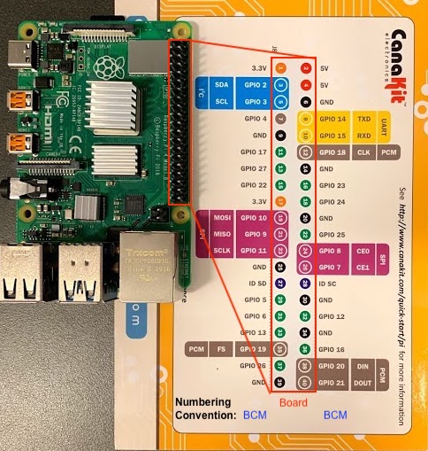
The kit comes with a GPIO Header Quick Reference Card, which corresponds to the physical header on the RPi as shown below. There are two numbering conventions on the Reference Card, Board and BCM, which are also marked in the figure. we follow the BCM (Broadcom) convention in all the tutorials.
Making things easier, the kit comes with a breakout board and a ribbon cable. Connect the GPIO pins to the breadboard using the ribbon cable and breakout board, like this:
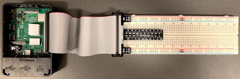
Now, you can develop your circuit on the breadboard alone. No entangled wires any more!
Breadboard
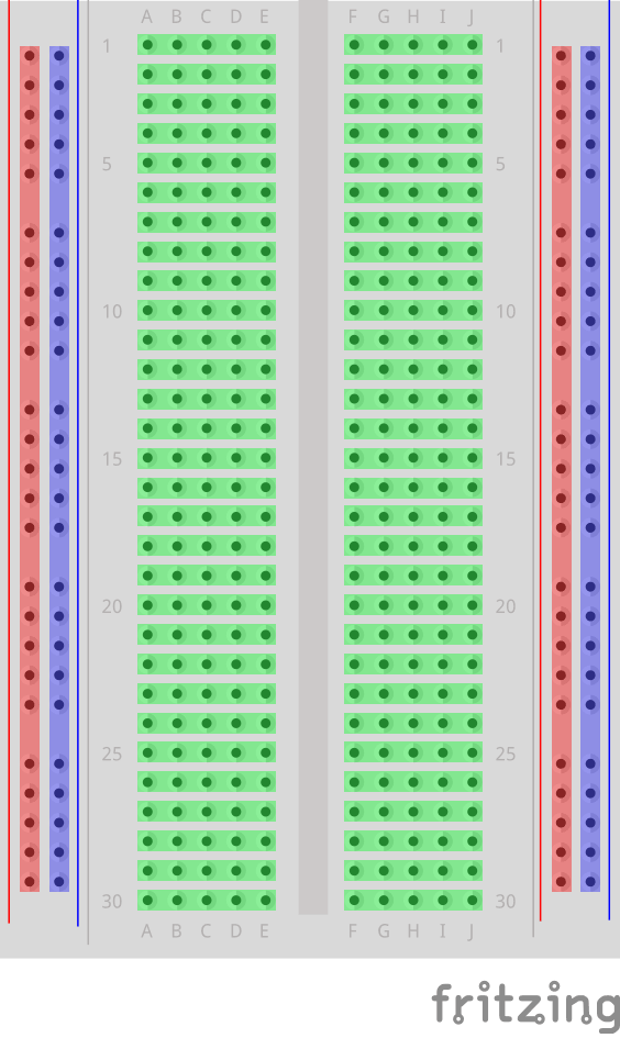
For those of you who have not worked with breadboard before, the figure below shows how the tie-points are connected. The Red columns are connected to the power. The Blue columns are connected to the ground. The Green rows are inter-connected, except for the gap in the middle.
Control an LED with a Timer
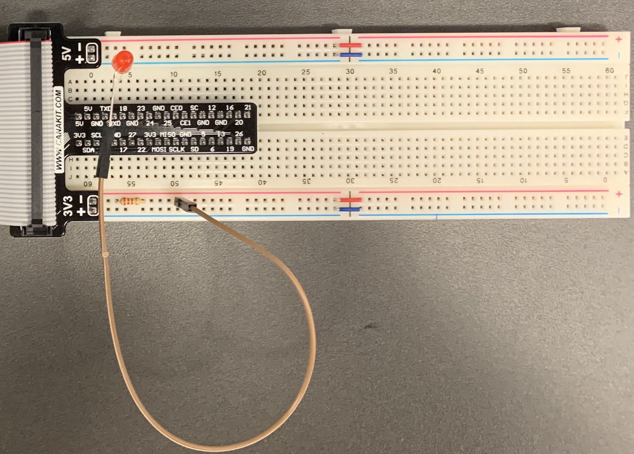
We will start by connecting an LED to the breadboard. We will control the LED with a timer.
- Set up the circuit following p. 9 of the Quick-Start Guide. The circuit should look like this:
- Copy & paste the following code into Thonny Python IDE that comes with the Raspbian OS. Alternatively, all the sample codes used for the tutorials are available at this Github Repository. You may download the repository to your local path.
import RPi.GPIO as GPIO
import time

GPIO.setmode(GPIO.BCM)

red_led = 18

GPIO.setup(red_led, GPIO.OUT)

while True:
    GPIO.output(red_led, GPIO.HIGH)
    time.sleep(3)
    GPIO.output(red_led, GPIO.LOW)
    time.sleep(1)
If you want to better understand the code above, you will want to read about the RPi.GPIO Python Module.
- Finally, run the Python script. You may run it with either the IDE or the terminal. To execute in the terminal, use the
$ cd /path/to/python/scriptcommand to go to where the Python scripts are stored and use$ python3 fileName.pyto execute the script. - Note that there is not a termination condition in the script, so it will run indefinitely. Press
Ctrl+Con the keyboard to terminate the process.
Control the LED with a Button
Now, we will use a physical button to control the LED.
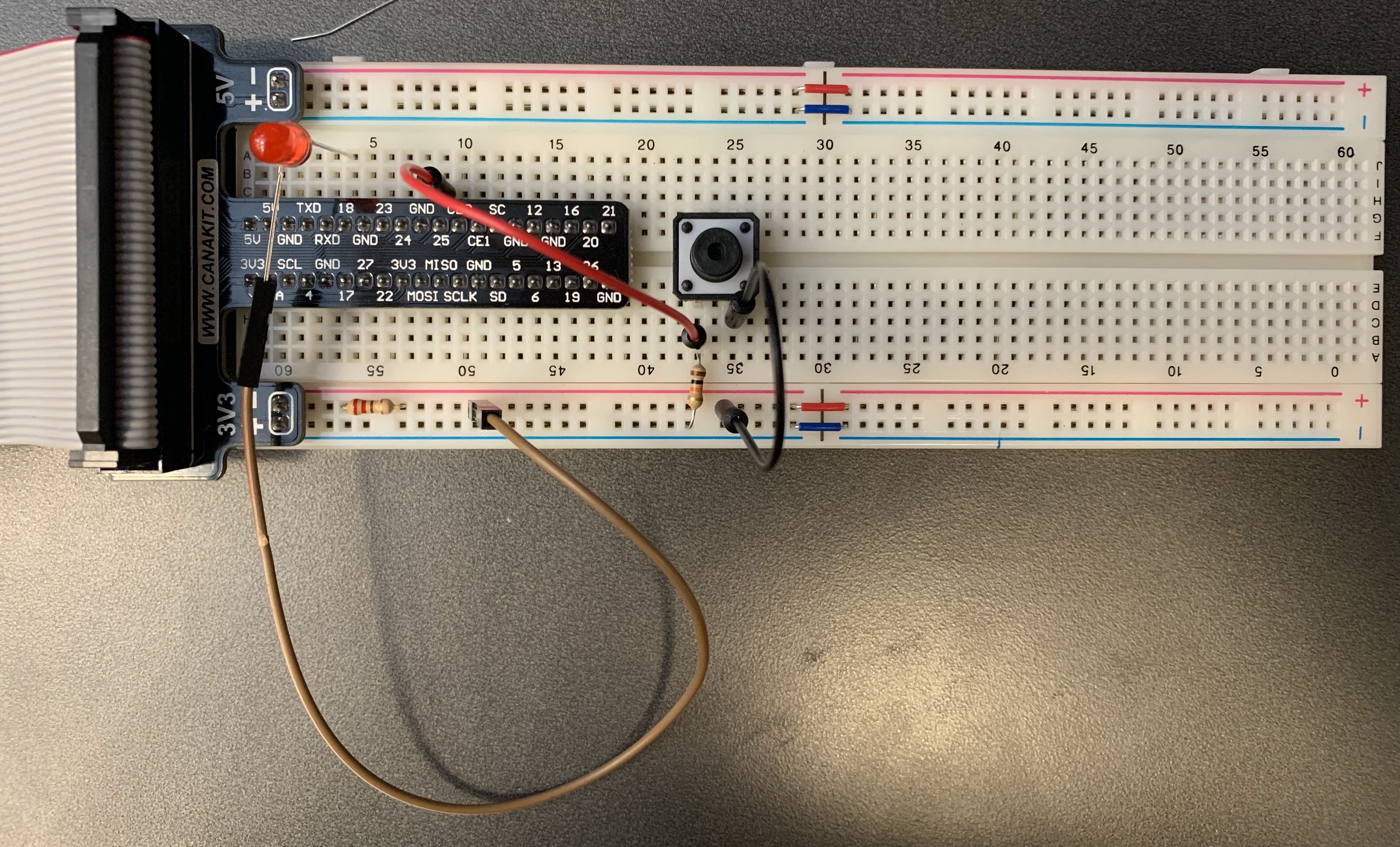
- Set up the circuit following p. 10 of the Quick-Start Guide. You may want to straighten out the four legs on the button. It is easier to press the button onto the breadboard that way. The circuit should look like this:
- You only need to modify a few line of codes to replace the timer with the button.
red_led = 18
button = 25

GPIO.setup(button, GPIO.IN)
GPIO.setup(red_led, GPIO.OUT)

while True:
    if GPIO.input(button):
        GPIO.output(red_led, GPIO.LOW)
    else:
        GPIO.output(red_led, GPIO.HIGH)
- One thing you may have noticed is that the LED stays in the last state when you terminate the process. That’s because the GPIO pins do not reset automatically. We can use
GPIO.cleanup()to restore the pins to their defaults states. Use the following code to catchKeyBoardInterrupt, i.e.Ctrl+C, and reset pins before exiting the process.
if __name__ == '__main__':
    try:
        main()
    except KeyboardInterrupt:
        GPIO.cleanup()
        sys.exit(0)
Putting everything together, the code looks like this:
import RPi.GPIO as GPIO
import time
import sys

GPIO.setmode(GPIO.BCM)

red_led = 18
button = 25

GPIO.setup(button, GPIO.IN)
GPIO.setup(red_led, GPIO.OUT)

def main():
    while True:
        if GPIO.input(button):
            GPIO.output(red_led, GPIO.LOW)
        else:
            GPIO.output(red_led, GPIO.HIGH)

if __name__ == '__main__':
    try:
        main()
    except KeyboardInterrupt:
        GPIO.cleanup()
        sys.exit(0)
Version Control with Git
To collaborate with your teammates, you may want to use version control for your codes. Read this Guide to create your own repository and learn how to manage your codes among the team.
Exercise:
- Vary the circuit by replacing the button with the Touch Sensor and the LED with the Buzzer Alarm.